

This post is part of the Hands on Ground Robot Design series. See here for the full list of posts/topics http://robotsforroboticists.com/hands-on-ground-robot–drone-design-series for information on mechanical, electrical, motion control, computing, sensors, and more.
Power System
The power system of the robot is key for making everything move and for powering all of the sensors and computers. Often reliability issues within a robot are from issues with wiring. There are several things we need to make sure of:
- All wires are properly crimped/terminated
- Connectors selected and fabricated need to be reliable
- DIN Rail terminal screws are all tight
- Should be easy to debug
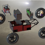
The first step in developing the power system is developing a block diagram of all the devices you have. This does not need to be a fancy schematic, just start getting things on paper. This step is very important for multiple reasons.
- Lets you verify all of the devices in the robot. This can also be shared with your team to make sure that all of the team agrees that this is the full set of components in the robot.
- Figure out the voltages required for each device. This lets you start mapping out what DC/DC converters are needed so that you can convert from your main system bus voltage to the other voltages needed in your robot.
- Determine all of the communication protocols for each device and how things will interface with each other.
- Does your computer have enough ports?
- Figure out what needs fused
- Figure out where connectors are needed and what the current rating of the contacts need to be.

Note: I created this diagram from memory for this post, and do not have all the detailed part numbers that I would normally like to have.
The above design has a shunt regulator. This shunt regulator helps prevent the system bus voltage from climbing when the motors are backdriven (such as when somebody drags the robot around). If there was no shunt regulator the voltage could increase (in particular when the power switch is turned off) and components in the robot can be damaged. When placing the shunt regulator you want it to be located in a place that will not get cut off from the motors, such as from switches or a blown fuse.
Battery Selection
In most systems (these robots included) you want as much energy density as possible. This allows the robot to have the longest run time possible in the smallest volume and mass. Often when you want lighter (or higher energy density) batteries the first choice is a lithium battery type. We needed to find a good lithium battery chemistry that would be stable and safe. This is particularly important due to the high duty cycle and frequent charge/discharge cycles of these batteries. We also wanted to avoid having to implement our own battery management system (BMS).
We ultimately selected Valence U1-24RT batteries. These batteries are a relatively safe chemistry and can be used as lead acid battery drop in replacements. They also come with an integrated BMS to help keep the batteries (and us) safe.


Power Distribution
For power distribution we used DIN rail terminals that are able to be shorted togethor to create bus bars of various voltages. The DIN rail also allows the network switch, fuses, relays, etc… to be mounted to it. There were two main locations in the robot that had these DIN terminals. The bottom tray of the robot had the main system and battery level DIN terminals, then a shelf was on top of this that had the DIN terminals for the outputs from the DC/DC converters and the estop bus.
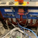
There are two Vicor DC/DC converters (partially visible in the top right corner of the below image). The two black fuse holders in the image below were on the input to the DC/DC converters. You can also see the black center pivot with a hollow bore that has wires passing through it to get to the other side of the robot. Those wires are mostly for the motor controllers and batteries.
Note, how each wire is individually labeled with what it is from (or the voltage needed). While time consuming to do this, having labeled wires greatly helps with debugging in the field. Also note the wire guides mounted near the terminals to help protect and control all of the wires.

Soft Start Circuit & Main Power Switching

When we built the robot we were very excited to turn it on. However after first turning the robot on, it immediately turned off. This was eventually determined to be due to the battery management system (BMS) trying to keep us safe… The motor controllers had a large (undocumented, and larger than expected) startup current due to high capacitance in the controller. When the BMS detected that high current (for a fraction of a second) it would shutoff the battery output until the load was removed. This led us to implement a soft start system that allowed the capacitors to slowly charge (through the 100ohm resistor), before turning the robot on.
This was implemented as a single switch (SW1) that when turned to the left was momentary (MOM) (for the soft start) and to the right was maintained (MAINT) (for normal robot powering). (The center position of the switch (SW1) is the off position.) The procedure to start the robot was to turn to the switch to the left for 1s to allow the capacitors in the motor controllers on the main bus to charge slowly through the resistor, then turn the switch to the right to engage the main contactor (R1) in order to actually use the robot and hold the main bus at the battery voltage. This switch was nice since it was designed that one side was spring loaded so it only held its position momentarily as you held it, and the other side held its position on its own like a standard switch.
In the image above you will also see that we use a “main contactor”. A contactor is a fancy word for a relay that is good to be used with high current motor loads. This lets us have a small switch with small wires for the user, and then the larger gauge wire is in the belly of the robot with the contactor.
Next Steps
Now that we have a power system, lets start with the computing and motor control design by clicking here.
Leave your comments and questions below.

Pingback: Hands On Ground Robot & Drone Design Series - Robots For Roboticists
Pingback: Motor Controls & Computing - Hands On Ground Robot Design - Robots For Roboticists