
Motor Controls & Computing – Hands On Ground Robot Design
by David Kohanbash on March 16, 2022
This post is part of the Hands on Ground Robot Design series. See here for the full list of posts/topics https://robotsforroboticists.com/hands-on-ground-robot–drone-design-series for information on mechanical, electrical, motion control, computing, sensors, and more.
Check out the post below for some pro tips on getting better support when talking with motor controller vendors.
Motor Controls
We used Copley BPL-090-30 and Copley ADP-180-30 motor controllers in these robots. The different controllers used were based on different robots and also based on function (wheels vs communications node dropper). One of the reasons I really like Copley drives is that they have a C++ software library, Copley Motion Library (CML) can be used (for a small cost) in Linux for controlling the drives via CAN. The BPL-090-30 had a higher startup current than the ADP-180-30 which caused some battery shutoff issues as discussed in a prior post.

To maintain modularity within our robots we had the motor drivers mounted near the motors as a module. This lets us minimize the number of wires that need to run around the robot and also create individual wheel/motor modules that can easily be replaced if needed. Each wheel/motor module just had a power cable and a CAN communications cable between the ebox and the modules. All of the motor controllers were on a single CAN network and were daisy chained to each other.
We use a Copley CAN-USB converter to communicate with the drives from the computer in the ebox. This module transitions from the computers USB port to the CAN network used by the motor controllers. We used the Copley CAN-USB for two reasons.
- It works well.
- It is made from the motor controller vendor. So if we ever need support, the vendor will not blame the USB-CAN converter as being the issue.
.

Note: Each robot had multiple communications (comms) nodes that could be dropped by the robot to build a comms network. In an early iteration we used two Copley motor controllers to control the comms Dropper.
In the above diagram you can see the power wires going to each wheel module, then the CAN network wires daisy chaining all of the drives together. The CAN wires had to go back into the ebox in order to transition to the rear of the robot. Not shown in the diagram above is the terminator resistor that is inside the USB/CAN box and also in the comm dropper at the end of the CAN chain.
Also if you look at the diagram you can see that it calls for shielded wires. This is for two reasons.
- Arguably, it is a good idea to use the shielded wire to avoid “random” hard to find errors in the future
- Motor controller vendors first question when you have problems is often, “Are you using shielded cables?”. The ability to say yes to that question so you can move on with debugging is nice, even though often the problem seems (and is) obviously not related to noise.

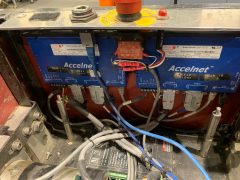
“Emergency” Stop
As part of the requirements we needed to integrate a wired and wireless estop (read here to see why this was not actually an estop) to stop the robots in case of any unsafe behavior. I also like to have a physical estop button to make sure a robot does not move while working on it.

In the image above there is a physical switch at the top in series with a relay that is controlled by the wireless digi radio estop. We did need to invert the radio signal to make the logic levels be as desired for operations. The terminal bus bar on the right of this image has the +12VDC turned on and off based on the state of the estop switches. From those terminal blocks we can feed the enable lines on the different motor controllers in the robot. There is also an LED indicator light tied to that bus for indicating robot state to the users.
Computing
There was a lot of early discussion about how to organize computing for the robots. In the end we decided to use multiple computers. Inside the robot chassis was an Intel NUC i7 8th gen computer (NUC8i7BEH). This computer was for “core” robot functions such as motor control, planning, safety systems, communications, etc..
The computers for object detection, localization, and mapping were integrated into the payload and was not in the main robot chassis. (This will be the focus of the next post).
We continued using the 8th gen Intel NUC throughout the project since it had a higher CPU clock speed then the 9th gen NUC. The 9th gen NUC had better threading/cores, however we preferred the increased clock speed since many of our algorithms were single threaded and could easy use a full core on its own.
By default the NUC comes with 1 ethernet port. However using the headers on the board you can add a second ethernet port, which is very useful if you want to split a computer between multiple ethernet networks, such as to talk to a high data rate sensor on a dedicated interface.
We had several NUC’s fail during the project. The failed units were for the following reasons (first 3 are related to the ground vehicles):
- Power – Somehow we destroyed the power supply on a NUC board. The computers were supplied power by isolated Vicor DC/DC converters which supplied relatively clean power to the computers. There were cases (such as when batteries were at a borderline voltage) that the computers may have had power applied and removed many times in a short time frame.
- Shorted RAM slot – We had several NUC’s that when we returned them for failure analysis we were told that pins in the RAM socket were shorting. Eventually we started securing the RAM modules better to minimize any vibration in the slot that could cause damage.
- Corrupted/Unknown – There were a couple modules that had no apparent damage, however would not boot at all. These NUC’s also had no signal to a monitor or keyboard.
- Physical Damage – This was primarily in the NUC’s that were on the drones that got physically damaged when the drones crashed.
As a general rule I try to avoid USB devices. You probably love the simplicity of USB, however after many projects using multiple USB devices, you will also try to avoid USB devices. I have had many projects where people insisted that USB is great, only to have them come to me months later describing their pain of getting the USB devices to work. Some of my issues with USB has been with the reliability of the connectors, identifying different devices (especially if you have multiple of the same device type), USB devices failing to be recognized with a new Linux kernel, USBc devices not be recognized or dropping connection (especially on NVIDIA Xavier/TX2's), etc..Next Steps
Now that we have a full robot system designed we will need to start talking about sensors and the sensor payloads in the next post in this series. See here for the next post on the sensor payload design.
See here to learn how to configure a motor with a Copley motor controller.
Subscribe to this blog to stay up to date with updates in this series!
Leave your comments and questions below.

Comments
[…] Motor Controls & Computing – Hands On Ground Robot Design […]