

This is part of a series of posts talking about some of the common LIDAR’s used in robotics. At the end of these sensor profile articles there will be a final post that compares the sensors based on data collected by each of the sensors.
Posts:
Evaluating LIDAR Guide
LIDAR Fundamentals
SICK TiM551 – LIDAR Overview
SICK LMS111 – LIDAR Overview
SICK LMS511 – LIDAR Overview
Hokuyo UTM-30LX – LIDAR Overview
LIDAR Review Comparisons
I hope this series (and particularly the final comparison post) proves useful.
Enjoy!
This post is going to discuss some of the fundamentals of LIDAR that are not typically covered in a basic tutorial. There are several reasons why people like using a LIDAR instead of a camera including, it works in the dark, much easier to process (algorithmically and computationally), and you can avoid having to deal with camera calibration.
Before I continue I just wanted to give a note about terminology. Some people use the term LADAR (LAser Detection and Ranging) instead of LIDAR (LIght Detection and Ranging). They are functionally the same, people just use different terms based on where they are and what they do. I think in the last 5-10 years more people have been saying LIDAR then LADAR.
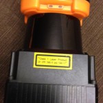
Eye Safety
I am putting this first so that you see it first. Not all LIDAR’s are eye safe. Many of the ones that are eye safe, are only eye-safe after being some small distance away from the laser. An example of a rating for an eye safe laser is class 1. Many LIDAR’s due to the scanning nature of the device are constantly moving so are less of a problem since the beam does not focus its energy in the same place. Some sensors that do not scan (such as a triangulation sensor) have a fixed beam that does not move and has a higher probability of being not eye safe. I actually know someone who has a missing spot in one of their eyes where they can not see due to laser damage.
How They Work
There are three primary methods for detecting distance. Most sensors use a time-of-flight method, sometimes combined with looking at the phase to determine distance.

Some sensors use just phase to get position by scanning with a modulated signal that changes in frequency, distance can be determined by looking at the frequency and phase. These sensors tend to be expensive.
There is another category of LIDARS that use triangulation. These sensors can typically provide extremely accurate distance (especially in the near frame), however they are often not eye safe.
In all of the cases there is often a spinning mirror to let the sensor move in a plane to get the 2D scan. There are sensors that will raster in 3D, producing a 3D point cloud.
You can see some great images of the inside of a LIDAR and the spinning mirror by clicking here
Reflectivity
The reflectivity of a surface is important for determining the maximum range of a LIDAR. It can also be used for detecting features in the LIDAR data. Many LIDAR’s in addition to providing an array of range data can also return an array of the reflectivity that it uses internally. A white surface will typically have a better return than a black surface (black rubber and coal are particularly bad). Another thing that affects reflectivity is the surface type. A smooth surface will typically reflect better than a rough surface.
There are several names for reflectivity. In addition to reflectivity it can be called RSSI or remission.
Spot Size & Multiple Returns
A lot of people forget about the spot size of the LIDAR. As the point of light exits from the sensor it expands and has a shape (often not conical). Some vendors will advertise a very small spot size but that might only be in one direction and not both directions. As the range increases the distance between each of the points increases. When you start getting range at a large distance (say 100m) the spot size of each point can be over 1m!

So what happens when a spot hits an item that is smaller than itself? In many LIDAR’s you just get the return from that smaller object. In many newer LIDAR’s you can get multiple returns. This means that you get the data from the first small object, and then you can continue to get data from subsequent small (or large) items.

Having multiple returns can be very important when dealing with rain, snow, dust, fog, seeing through tree foliage, etc..
Laser Frequency
Different types of LIDAR applications typically use different wavelengths for the laser.
Ground based systems typically use 500-600nm.
Air based systems (used for GIS) typically uses 1000-1600nm. The larger wavelength is good for penetrating clouds and stuff. However a smaller wavelength improves the detection of smaller objects.
Choosing a wavelength is all about which wavelength has the penetration you need, and the maximum power you can use (either legally or to stay eye safe).
Interference Between Sensors
You can not have the beams from multiple LIDARS in the same plane or you will have problems. There are two solutions.
1. Put the sensors out of plane with each other. So they are tilted at different angles.
2. Many sensors have a sync pulse that you can connect between multiple sensors so they will coordinate amongst themselves to avoid interference.
Other Issues
– Watch out for puddles, very bright “sun” reflections, bright snow, etc.. – These can all cause invalid points or bad readings.
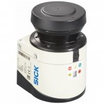
All of the images in this post are from the SICK LMS511 Operating Manual. The numbers/comments I mention in the post above are not necessarily related to the LMS511.

Pingback: Evaluating LIDAR Guide | Robots For Roboticists
Pingback: SICK TiM551 - LIDAR Overview | Robots For Roboticists
Pingback: SICK LMS111 - LIDAR Overview | Robots For Roboticists
Pingback: SICK LMS511 - LIDAR Overview | Robots For Roboticists
Pingback: LIDAR Review Comparisons | Robots For Roboticists
Pingback: Perception in Smoke, Dust or Fog - Robots For Roboticists
Pingback: SICK LMS Full LIDAR Teardown - Robots For Roboticists
Pingback: SICK LMS full LIDAR teardown – Robot Enthusiast
Pingback: LIDAR vs RADAR: A Detailed Comparison - Robots For Roboticists