

Hi all
This is just a quick post on how to increase the range of your wireless communication system. There are several ways to do it and they mostly apply no matter what frequency you are using. We will discuss several ways to do this below. We will also discuss some of the legal limits for how powerful your system can be.
You can use tools such as the Ubiquiti Airview or OmniWiFi to view how strong your signal is and what signals are in view. Or you can use less advanced software tools that use your computers wireless card. In Linux the command to check signal strength of networks in range is “sudo iwconfig wlan0 scan” where wlan0 is your wireless card device name.
Ways to boost your signal
Loss Reduction
The simplest way is to reduce the loss in your system. This is often from two sources; the cables and the connectors.
Cables – Try to use the lowest loss cable that you can use. Typically the lower the loss in the cable, the more it will cost, and the thicker and less flexible the cable will be.
Connectors – Minimize the number of connectors that you use and avoid using adapters to change connector types. Each connector and adapter interface represents a signal loss (called an insertion loss) in the final output. A general rule is that every connection of the same type (ex. N to N) is 0.25dB of loss and every adapter between connector types (ex. N to SMA) is 0.5dB of loss.
Clean your connectors – A common problem that most people ignore is cleaning the threads and inside of the connectors. When a connector is used several times a metal powder can form on the inside of the connector “shorting” the center pin to the housing. The best way to clean the connectors is with denatured alcohol (isopropyl alcohol can also be used but it leaves a film behind which is not ideal) and cotton swabs (often called Qtips). Be careful not to bend any pins!
Purchasing your cables and connectors from reputable sources is important. Buying the cheapest connector you find can result in reduced signal quality for no good reason.
Antenna
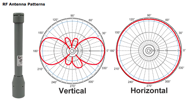
The next way to increase your range, is to use an antenna with an increased gain. You can get omnidirectional antennas with different gains that transmit in a torus pattern (they do not transmit directly above or below the antenna, that area is called the null space). As the gain increases the height of the torus transmission pattern decreases, however the range (diameter of the torus) increases.
You can also consider a directional antenna for increased range. These antennas focus the RF energy in a specific direction to extend the range. As with the omnidirectional antennas as the gain increases the directionality of the antenna increases for a tighter window. If the directional antenna is not pointed perfectly in the right direction communications will suffer.
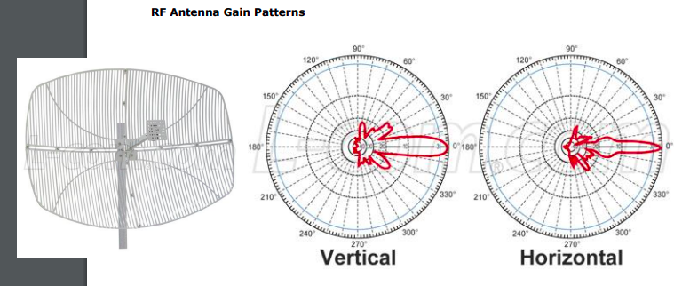
Often a happy medium for long distance comms is a patch antenna. Directional antennas are often <15degrees horizontal beam pattern, patch antennas can typically be up to 120 degrees.
When it comes to antennas it is important to visualize the transmission pattern. For example if a boat is rocking in the waves, a high gain omni antennas might not be great as the boat peak’s and leaves the toroid, then comes back down into the toroid, just to leave comms again with the next wave. Another example is with surface to air communications. With a higher gain antenna as the aircraft gets closer you will loose comms, and certainly in the null space overhead the signal will not be as strong (if any).
The other thing that helps antennas a lot is increasing the height and avoiding obstacles in the line-of-site (LOS) path between the antennas. If you can increase the height and avoid breaking LOS you can get a much better signal. When you determine LOS you need to remember the Fresnel zone. The Fresnel zone is an area above and below the LOS line that should be clear for maximum radio transmission quality, however it is not always possible for that area to be completely free from obstruction. As a general rule you should make sure to have less then 20% blocked however communications should still work with up to 40% of the area blocked. Having an area in the center of the freznel zone is generally not as bad as if you are blocking near the transmit or receive ends of the signal.


The easier way to figure out the center diameter of the fresnel zone for 2 aligned antennas is:
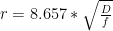
r= radius in meters of the largest center point
D = distance in km between antennas
f = frequency of the signal in gigahertz
Another thing to think about with antennas is polarization (the direction the wave moves). Generally you want the transmit and receive antennas to be polarized the same and physically oriented in the same manner. Common polarization’s are vertical, horizontal and circular. With some radios, such as 3 chain MIMO*, you can have the other two antennas be vertical polarized, and the center antennas be horizontally polarized for maximizing your chances of good signal reception.
*MIMO is a method of using multiple transmit and receive antennas. Based on realtime conditions the antennas can all be sending the same information or different information. This lets the radio handle interference better by sending the same data from all/some antennas at the same time. But if there is minimal interference, the radio can transmit different data at the same time from each antenna. The number of “chains” is the number of antennas.
Signal Amplifiers

Signal amplifiers sit between the radio and the antenna and can inject power into your transmission to increase the output power of the signal. This is often one of the most effective ways to increase power. The downside is that the signal can gt distorted and you need to provide more power for the amplification as opposed to just using an antenna with a higher gain.
Wireless Device/Radio
This might not always be possible but you can consider changing the radio you are using to get a higher output power model or to operate with a different frequency if you need increased range, penetration, or data rate.
As a general rule as the operating frequency decreases, the range increases and you get better obstacle penetration. As the frequency increases you get a higher bandwidth (more data), and a smaller antenna.
Legal Limits
There are also legal limits for how much power you can output and what frequencies you can operate on. The information below is for the USA (While I think this is correct I make no guarantees).
Frequency Limits
The standard frequencies for open use are known as the industrial, scientific and medical (ISM) bands. These bands can be used freely as long as you do not interfere with other devices.

The 900MHz radios we typically use in the United States are not allowed in many parts of the world. Some other parts of the world have spectrum put aside with similar performance.
| Location | Bands |
|---|---|
| Australia | 920 MHz |
| China | 779-787 MHz |
| Africa & Europe | 863-870 MHz |
| Japan | Nothing |
| North America | 902-928 MHz |
Power
The maximum allowed (ex. for unlicensed 2.4GHz FCC ISM band) transmitted power that gets fed into the antenna is 30dBm (which is 1W).
The maximum allowed radiated power is 36 dBm (4W).
To get the maximum radiated power you just add the gain of the transmit power to the gain of the antenna.
There are specific exemptions from this rule for the 2.4 and 5.8GHz ranges if the equipment are fixed point to point links (which robots are often not). You can get more details at www.afar.net/tutorials/fcc-rules/.
Remember that it is your responsibility to make sure these rules are followed and you dont make the FCC unhappy.
If you need to transmit at higher power levels it is possible to get exemptions from the government (In the USA that would come from the FCC frequency coordinators).
If you are using a MIMO radio, the power limit is based on the sum of all the transmit antennas. For for a 3 chain MIMO radio, each antennas can transmit at 0.33W to stay below the 1W limit.
Also remember that in some environments maximum power will yield worse comms. For example in a subterranean (SubT) environment having all that powerful signal bouncing off from the walls can create a lot of interference and can also inundate your receivers.
Here is a good video about antenna fundamentals:
Here is a good video explaining decibels (dB’s):
A good source for RF equipment (connectors, amplifiers, antennas, cables, etc..) is L-com.com or www.streakwave.com.
Now that you know how to setup antennas and all about signal propagation, click here to learn about networking and how to use the hardware that was just setup.


Pingback: Wireless routers for robots - Ubiquity | Robots For Roboticists
Pingback: Networking for Robots: A crash course | Robots For Roboticists
Pingback: Antenna Seperation: How Close Can You Go? - Robots For Roboticists
Pingback: Antenna separation: How close can you go? — botmarkt
Pingback: Networking for Robots: A crash course - Robots For Roboticists