Copley Motor Controller Review
by David Kohanbash on October 22, 2014
Update: Click here to learn how to configure Copley motor drivers
Hi all
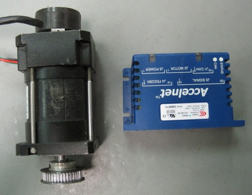
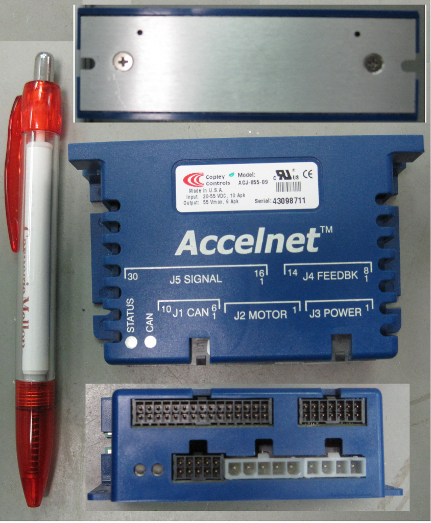
This is a post about the Copley Controls motor controllers. For this review I will be using a ACJ-055-09 (55Vmax and 9Apeak) motor controller (I love when product names mean something useful) with a 3 phase DC brushless motor. This is a good controller for distributed motion control.
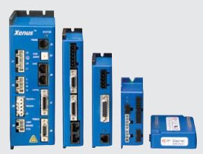
Copley makes several versions of their drives for brushed, brushless, stepper, and AC motors. There is also an “R” line of drives for their rugged products. There are also several form factors available including panel mount and board mount. For this review I have a panel mount drive. There are several types of panel mount form factors, I am using the squarish one and not the rectangularish ones. There is also a “pro” line available that has things such as more options for communications (including etherCAT) and more feedback options. The standard versions have RS-232 serial and CANopen. There is also a nice mode where you can connect all your drives via CAN and then communicate with one of the drives via RS-232. The drive will then forward the commands received via serial over the CAN bus to the other drives. This is a pretty nice feature. For controlling a motor there are generally 3 options: torque (ie current), speed, and velocity control.
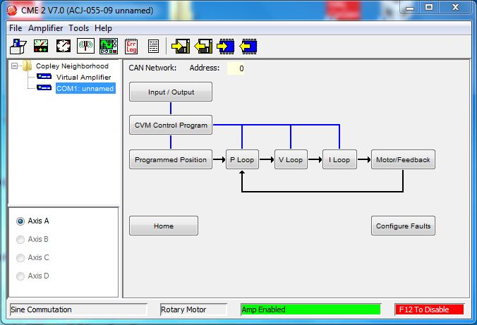
I am using the Copley Motion Explorer 2 (CME 2) version 7 in this review. Using the tools from the vendor is typically useful for commissioning a drive, tuning a motor, or just doing a quick test on a motor. It can also be used as the primary interface in some applications (such as a demo of some mechanism). Here is the user guide which I did not really read.
When you start the CME 2 software, before you have a chance to do anything a popup window comes up reminding you that you can press F12 to disable motors (you need to be careful since some new laptops default to hot keys and make you press Fn to get the F* keys). This might get annoying after awhile, but I like it and think it is great for safety to know how and be able to quickly stop a motor. Once you are using CME it has this printed in the lower right of the screen as a reminder.
The first thing that you typically do with a new motor is run the setup wizard. The CME setup wizard is really easy and fast to use. It lets you select the type of motor (brushless, stepper, linear, rotary, etc..), the commutation options and the feedback type (encoder type/source). For the commutation options if you have hall sensors and an encoder it gives you a choose for sinusoidal, estimated sinusoidal, or trapezoidal commutation. If you say you only have hall sensors you get to choose from estimated sinusoidal, or trapezoidal commutation, and to use back EMF or halls for velocity estimates.
The setup was very easy and quick but did not prompt for max values such as velocity and current! To configure all of those settings (and gains you need to click through the flow diagram on the main screen (which is mostly organized logically). It is easy and intuitive to use, but some of that should be part of the initial setup and not require you to go through the flow diagram. Certain parameters such as max velocity and max current are critical so you do not destroy your motors and gear boxes and should definitely be in the initial setup wizard.
The auto phase wizard is the best I have seen in any motor controller software. This lets the drive detect motor wiring, number of poles, and hall wiring. This is very useful since every motor and controller company has a different idea about which phase is A, B, or C. It also helps if you mess up the wiring. It is easy to use, intuitive, and the graphics are great. But I don’t understand why the initial setup wizard does not prompt you to run this!
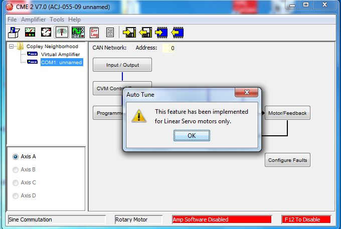
The next thing I wanted to do was to auto-tune my motor. Unfortunately I got an error saying that it can only auto-tune linear motors. This is ridiculous as pretty much every other vendor can do this and I would guess that there are far more rotary motors then linear motors in the world. WTF!!
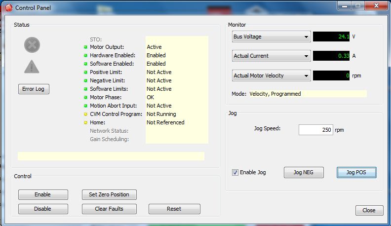
So finally I was ready to spin the motor, so I open the control panel. It works like any other control panel. It lets you spin the motor and shows you some parameters from the drive. The annoying thing is that it only lets you spin the motor in the mode you said you were going to use in the initial configuration (position, current, or velocity) and you can not change modes from the interface. In position mode you can set a jog rate (jog is a fancy work for spin), acceleration, and deceleration; however you can not tell it to go to a specific position. How does that even make sense for a position mode? In current mode you can specify a current and say jog and it works — great! In velocity mode it only lets you set a jog speed, you can not specify an acceleration or deceleration rate. Why not, you can do it in position mode, why can you not do it in velocity mode where it also makes a lot of sense to have? Another annoying thing about the control center is that it requires you to hold down the jog button. You can not just send a command and then just tell it to stop.
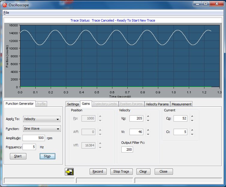
The scope function is really nice. The scope is useful for monitoring motor data and tuning the motors (which you must do manually since the autotune is a FAIL!). It lets you configure various motions (sinusoidal, steps, etc..) with a “Function Generator” tool, see what happens on the scope display, and change the gains from the same screen. Really nice. In this tool you can zoom in on data with your mouse and use cursors to analyze the data. Clicking the button that looks like an arrow going into a door (at first I thought that would exit this scope tool)(if you squint maybe it looks like a disk) will save a CSV file, a tab separated file, and some custom data file of the current data set (a .sco). One weird thing is that you can not open the scope file (.sco) back up in the scope to look at the data. If you want to open a scope file for review you need to go to Tools->View Scope Files. This other tool will show you the settings used to get the data and also give you the cursors and analysis tools from the main scope tool. All in all, it is a very good tool, and one of the best scope tools I have seen for a motor controller.
CME includes a serial terminal for talking to the drive directly. It is pretty bad and only lets you enter one command and see its result. You can not really see a scrolling list of your commands and the responses. While you can always use a different terminal program, it is nice to be able to view motor information and use the terminal at the same time when working with the motor.
If you save the motor drive settings to your computer it is in a human readable format and has a description next to each field. Very Nice!
There is a option under tools where somebody can login. I am not sure what it is for. If you know please leave a comment below.
After this experience I am over all impressed with the drives and would use them. They have a good form factor, look and feel solid, and an easy to use interface. Looking at the serial communication protocol it looks pretty simple to develop a software driver to talk to the drives for robotic control. Using CANopen is obviously more complex but looks equivalent to other commercial motor drives.
Now that you have read the review, click here to learn how to configure a Copley motor controller.
The Copley drive and motor was lent to me by a distributor. I do not get to keep it.




Comments
[…] Controls Click here for a full review of a Copley motor controller. Copley is a newer player in the game however I have been impressed by their products. They are […]
[…] Main image is from my Copley motor controller review. […]