
Common Robot Tests – Field Testing Series – Part 6
by David Kohanbash on February 11, 2014
This post is part of a series on testing robots with a focus on field testing. It will start with why we test robots, work its way through planning for a field test, to performing the test, and finally what to do after the test. We will conclude with a description of many common tests that we subject our robots to and how to perform them.
I hope you enjoy this series and please leave comments below.
Links:
Why Test Robots? – Field Testing Series – Part 1
Designing for Success – Field Testing Series – Part 2
Test Preparation – Field Testing Series – Part 3
Test Execution – Field Testing Series – Part 4
Test Analysis – Field Testing Series – Part 5
Common Robot Tests – Field Testing Series – Part 6
—————————————————–
There are many types of tests that can be performed on a robotic system. Here is a list of common tests, it is in no way complete!
Component Level
Component level testing is one of the hardest to define since it changes for every type of component.
Some of the common component tests include:
Use
Does the system work? For example if an arm needs to lift 10kg, can it lift 10kg? This is often a qualitative metric based on if things work as expected. There is also a quantitative component to this test where numbers are established to meet specific system requirements.
Destructive
This is where you test a component or system until it breaks. This is common for mechanical systems where you want to know when it will fail and/or break. Destructive testing is often performed while in the design/build phase of a robot.
Thermal
Testing components both at operating temperature and at the high and low extremes is important. Tolerencing of mechanical systems is very important and I have seen this cause many problems. Temperature also can affect electronics and batteries. The current draw and resistance of components/batteries can change significantly with temperature.
Power / Current
The power that a component uses, or that the complete robot uses is good to know. By finding the current draw of each system, and the power used, you can have a baseline that can then be used for detecting faults and sizing batteries. Knowing the current draw of the locomotion system can be especially important for detecting faults, excessive vehicle slip, and motor torque.
Endurance
Determining how long a system can operate lets you establish reliability. When you do an endurance test, make sure the robot/component is seeing realistic conditions. For example if you are testing an autonomy system in a wide open field you are not really testing obstacle avoidance, as there are no obstacles to avoid.
Stress
Stress testing is the idea of operating at the performance extremes of the device. While in endurance testing you are focused on duration, here you are focused on performance.
Vacuum
This is not a common test for earth based systems. However when developing robots for space this is a critical test. By placing a component/system in a vacuum you can see the affects of operating in space. For a true “space” test, you do a thermal+vacuum test, which is where components really start to fail.
Wheel Testing
I know this is really just a component test but I felt like breaking it out. Many people ignore the wheels since people have been making wheels for thousands of years and we think we have an intuitive grasp of how they work. The reality is that wheel design can be complex, even the NASA MSL Mars Robot has suffered from this assumption. Performing endurance and stress testing on a wheel can be very informative. The other part of a wheel that is often ignored is the growsers. Changing growser size, shape, and pattern can have a significant impact on the wheels ability to climb slopes and operate in difficult terrain.
Tip Over
Knowing the tip-over angles of your robot is important so that you know the safe operating limits of the robot in both of the horizontal axis (I guess that would be called width and length). Their are often two tip over points that we care about. The static tip over for when the robot is not moving, and the dynamic tip over point for when the robot is operating. These can often be calculated and then verified through testing.
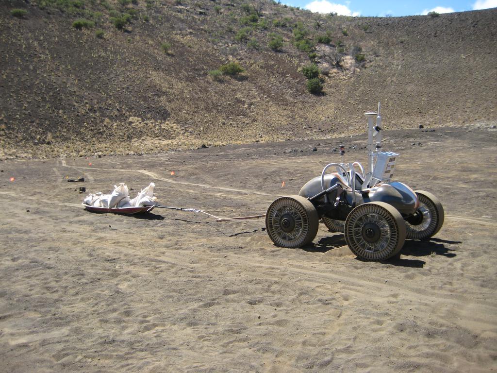
Drawbar Pull
Drawbar pull is a test that helps characterize the entire drive system of a robot on a given terrain. The basic idea of this test is to make the robot drag a weight, while you measure how much force the robot can pull while continuing forward motion. A standard way to define when forward motion stops is to look at the final plot of force vs slip (
For a drawbar pull test there are three main components that you need.
1. Adjustable weight to drag behind the robot. Based on how adjustable the weight is controls the resolution of the test.
2. Load cell to measure the force between the weights and the robot
3. Actual robot position. This should be a way to determine the robots position. This is usually from a external reference, such as from a motion capture or LIDAR system. One good method of tracking position is with a Leica Robotic Total Station (the total station can very accurately get position by tracking a prism on the robot). Here is a good paper that describes draw bar pull in more detail
Slope Climbing / Slip
Slope climbing is the ability of a robot to ascend or descend a slope. This is also highly dependent on the slope material and robot design. There are several versions of this test. You can try finding the maximum slope that you can ascent straight up, or you can find maximum slope that you can ascend using switchbacks and driving up from an angle. When descending a slope we often look at slip (as defined above).
Obstacle Avoidance
For obstacle avoidance there is not much to say as the title captures the test. You can set up various obstacles of various sizes and make sure the robot avoids them. One thing that people often forget is negative obstacles. I have seen many robots that could successfully navigate around rocks, trees, and cones only to completely fail when encountering a hole or cliff.
Another thing to be aware of is obstacles that the robot finds that you might not see. For example if you are operating in tall grass the robot might see that as an obstacle and refuse to drive.
Position Estimation
Without good position it is difficult for a robot to get anywhere. Some position estimation systems are easy to test, such as GPS based system or from a commercial inertial navigation system (INS).
When you develop your own position estimation system that is where the fun begins. Often to evaluate position you can drive around for a while and then compare estimated position with ground truth from a GPS, INS, or total station.
Other ways to evaluate position without the external references is to command a set of motions that ends where the vehicle started, and by marking the ground you can evaluate how close the robot came to the expected start/end position. Another way is to again mark the start position of the robot (and maybe some mid points) and command the robot to drive a circle; you can then see if the vehicle is drifting or if it is maintaining the circle. The circle test can also shows imbalances with the mobility system.
Also from experience when you are driving on a more-or-less flat surface you can monitor the Z (up<>down) axis to make sure it is not climbing. Seeing the Z axis drift is a good indicator of problems with the position estimate.
There are many other tests that you can do with a robot, and developing an all inclusive list is difficult. I hope these are useful and feel free to add more tests in the comments.
Image Source: http://www.frc.ri.cmu.edu/projects/lri/scarab/images/MK_testing/IMG_1477.html

Comments
[…] – Field Testing Series – Part 4 Test Analysis – Field Testing Series – Part 5 Common Robot Tests – Field Testing Series – Part 6 […]
[…] – Field Testing Series – Part 4 Test Analysis – Field Testing Series – Part 5 Common Robot Tests – Field Testing Series – Part 6 […]
[…] – Field Testing Series – Part 4 Test Analysis – Field Testing Series – Part 5 Common Robot Tests – Field Testing Series – Part 6 […]
[…] To measure drawbar pull you can typically tie a rope to the center rear of the vehicle (near where a hitch would go) and attach the other end of the rope to an adjustable load. This adjustable load can either be a programmable load (such as a particle brake) or actual physical weights that are added. At the most basic level this will tell you how much the robot can pull. In practice we look at the amount of slip exhibited by the wheels for different loads. To do this we need to have an independent way of determining robot position, this is often done with a long string potentiometer or a total station. See this post for more information on drawbar pull testing. […]