
Creating Wire Harness Diagrams
by David Kohanbash on April 3, 2014
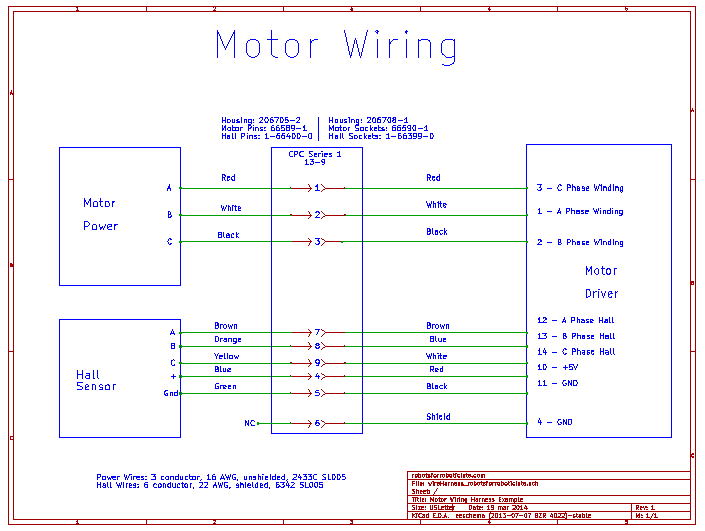
(See full size wire harness diagram here)
Hi all
So it is time to think about wiring up your robot, one of the key steps before you begin is to develop a wiring diagram. A wiring diagram is not only needed for wiring the robot but is also a valuable resource to have if you ever need to modify the electrical systems in the robot or when you are debugging a problem.
While I am only talking about the diagram there are a lot of standards about how to design and build a harness.
So what should go on the wiring diagram? The simple answer is everything that you will need to identify what each conductor in the cable is and how to recreate the wire harness.
A more detailed answer is that it should have the following:
Cable: Number of Conductors, Gauge, Shielded vs non-shielded, Length
Connectors: Connector part number, pin/socket part numbers
Wires: Color (or number), function
Harness: Which wire is connected to which pin, shields
In the example image above you can see the connector box in the middle that shows which side are pins and which side has sockets (the sockets are on the powered side). You will also notice that the connector, pins, sockets, and wires are described and have part numbers. Another critical thing is having the data and revision on the diagram.
There are several software packages that can be used for drawing harnesses. My preferred approach is to use an ECAD program such as Altium or KiCad and draw the wiring diagram in a schematic window. I usually create parts that looks like <- and -> to use as pins and sockets, and then draw a wire to connect them.
There are several specialized tools (that I have no experience with) for doing wire harnesses including SolidWorks Electrical, MentorGraphics VeSys, and Zuken E3.

Leave a Reply